Icarus
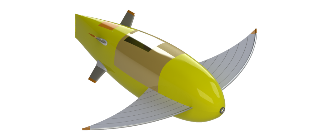
Pictured: CAD Rendering of Icarus
For eISR 2020, we have decided to rename our submarine to Icarus. In Greek mythology, Icarus was given a set of wings to escape Crete and fly between the sea and the sun. Like its namesake, Icarus was built to escape the propeller realm and hope to fly low enough to remain below the surface. Icarus also fits this submarine as the team was warned to stay away from non-propeller submarines as they were “too difficult”. The name represents our desire to follow our beliefs and take confidence within ourselves to take flight and create Icarus.
General Arrangement
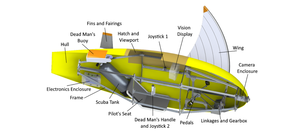
Pictured: General Arrangement of Subsystem Components
Sub-Teams
Hull
The hull is the defining component of the submarine, visually and functionally. This year’s design is reflective of the team’s need for increased space due to the complexity of a non-propeller design. The hull itself was designed as the shape that fills two different, intersecting and perpendicular airfoils, with elliptical cross-sections of varying size connecting the airfoils along the length axis. The hull is 2.65 meters long from bow to stern, representing a significant reduction in length from Skookumchuck Mk. V to help reduce the overall amount of material required to construct the hull. The hull is 0.62 meters in beam.
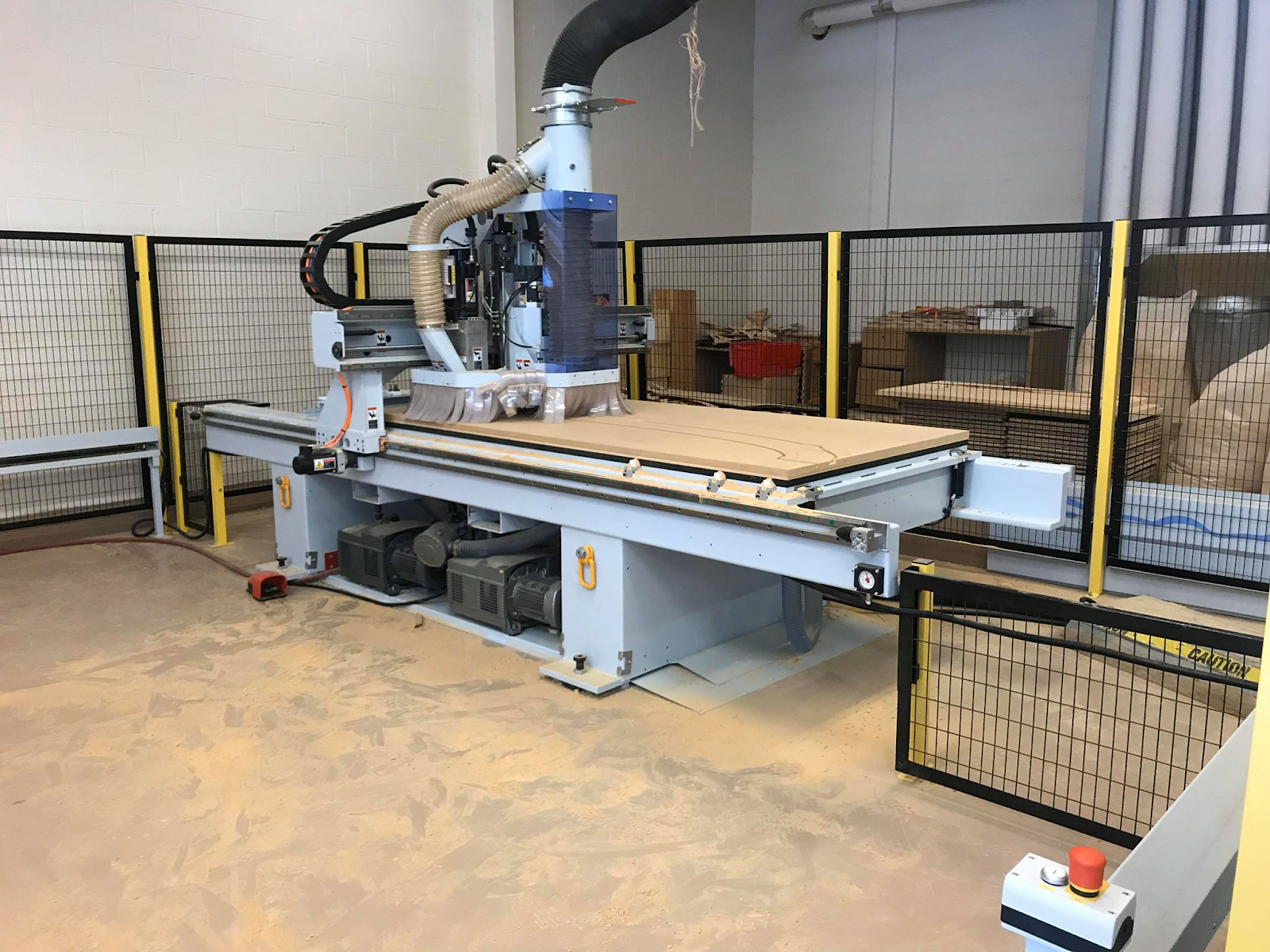
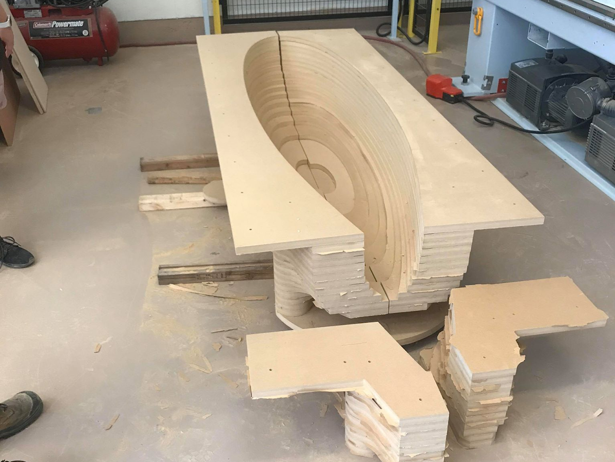
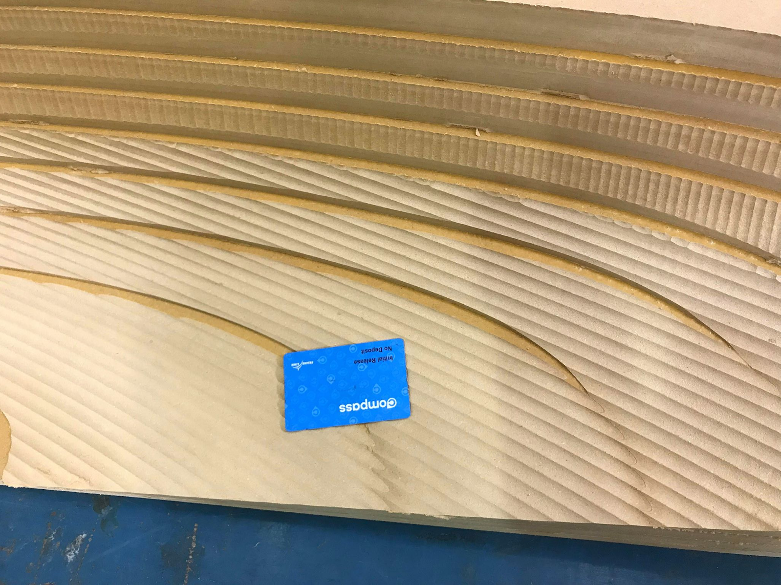
Pictured: CNC Machining Process - Glued MDF Mold - Mould Post CNC Process
Frame
The frame of Icarus was designed as a rough linear approximation of the hull’s curvature. It serves as the mounting structure for all subsystems and components. Aluminum extrusion is used extensively throughout the submarine in addition to 4 plate metal rings. The frame cross bars were divided by the rings into 3 thirds denoted as the front, middle, and back. A full internal frame had never been attempted by the team before, and posed many new and unique challenges for our team.
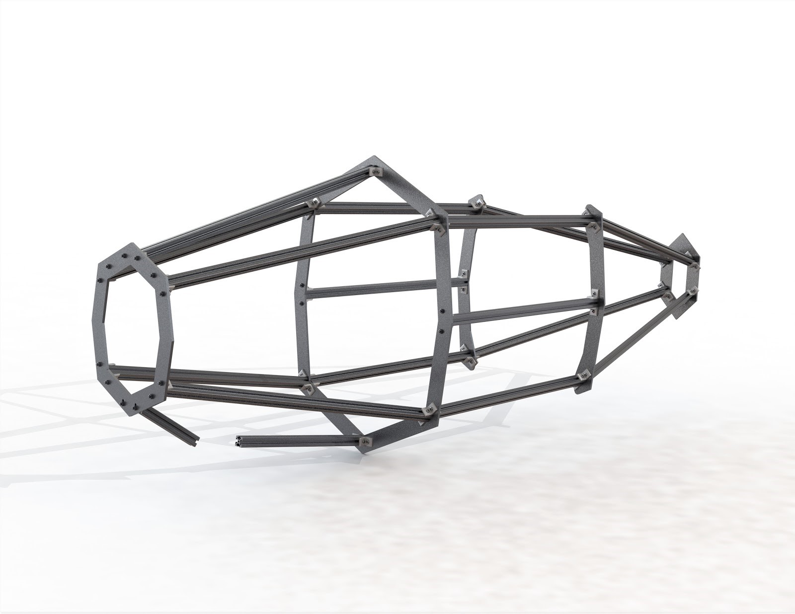
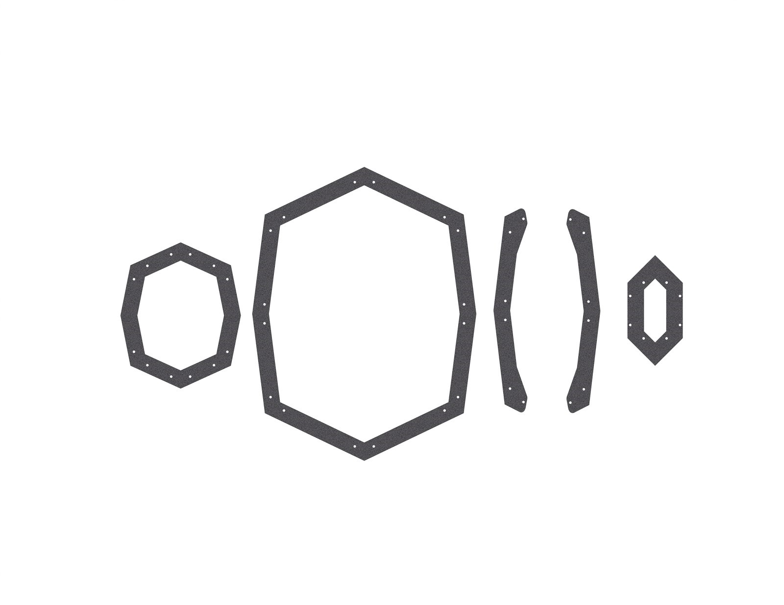
Pictured: CAD model of the frame - Frame rings ordered from front (ring 1) to rear (ring 4)
Propulsion
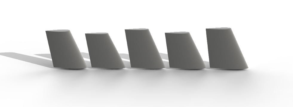
This rendition of SUBC’s design implements a rajiform propulsion form (biomimicry of manta ray anatomy) to innovate in propulsion. Rajiform motion is recognized as being a highly efficient form of thrust within manta rays, and the inclusion of this motion allows for a total system reconfiguration within all systems of this year’s design.
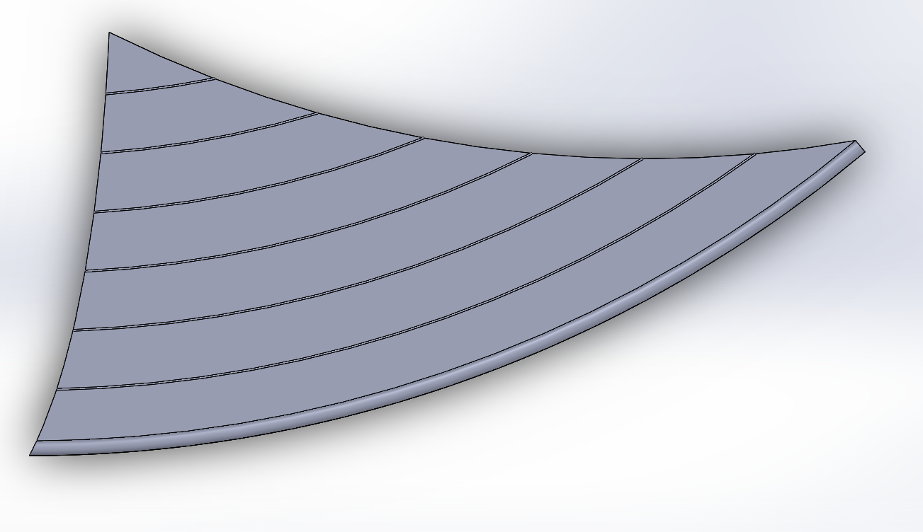
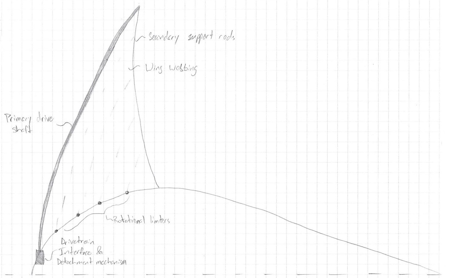
Pictured: SOLIDWORKS wing model, plane view - Conceptual wing design sketch
Drivetrain
The drivetrain system consists of a set of pedals that can be adjusted vertically and axially for the pilot to transmit torque through a chain to a double output right angle gearbox. Each gearbox output is connected to a set of 6-bar mechanical linkages, one set mirroring the other, which converts their rotational inputs into “flapping” in a 45 degree sweep, with the angle varying sinusoidally. The outputs connect directly to the wing through a locking folding joint.
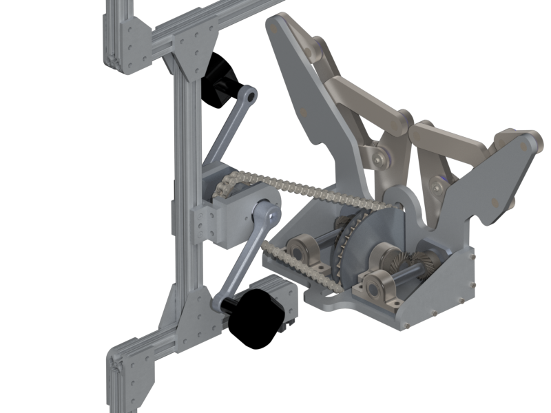
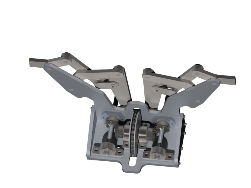
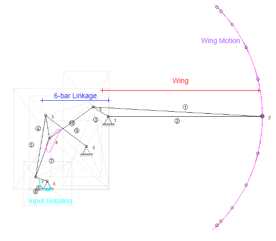
Pictured: Drivetrain System - Gearbox Housing - Linkage Diagram
Steering
Given the width of our overall submarine, we needed to be able to induce roll to fit within the slalom course during competition, differing from our previous model which only provided pitch and yaw. We considered 2 different fin orientations to achieve this movement, traditional cross-form and X-Form fins. After further research, we found that the X-Form model allowed for higher angled turns of the sub with less change in fin angle. The fins we selected are based on the symmetrical airfoils NACA 0012, 0014, and 0016.
With the need to control all ranges of motion we opted to use 2 joysticks, one for pitch and yaw, and the other for roll. We designed the code for four steering motors on the Arduino IDE. In order to obtain the desired motion each fin we broke down all combinations of possible directions of motion into a series of input and output tables to use when constructing our code, based on the relative angle of each fin.
Pictured: Renders of Proposed Fin Designs
Computer Aided Vision (SubSee)
Since this year’s submarine has the drivetrain in the front, and the pilot is in a recumbent pedaling position, they cannot navigate through a transparent nose of the submarine. To counter this, our system has an LCD screen which is positioned in front of the pilots face which displays a live feed from a camera module mounted on the bow of the submarine. Data from sensors are transmitted to a Raspberry Pi which records each dive and displays the overlays on top of the live feed. These overlays include navigational data from the Data Acquisition (DAQ) system such as pitch, speed, and depth as well as informational data such as a low battery indicator, drivetime clock, and motor or light activation indicators.
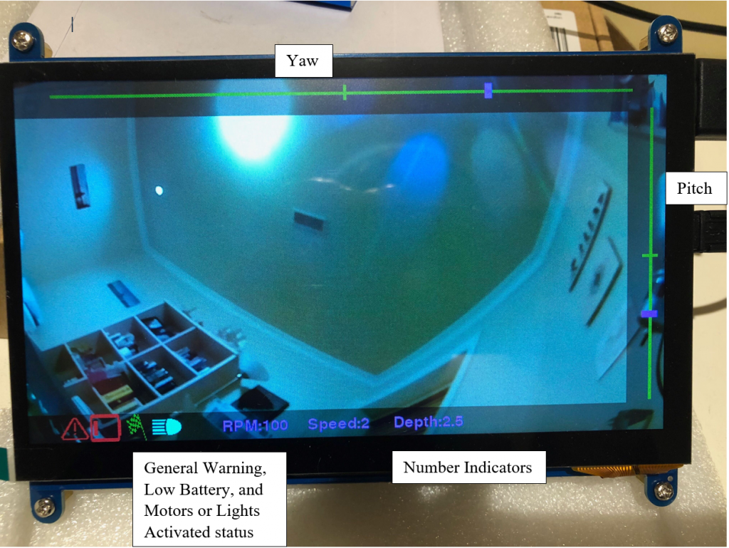
Pictured: SubSee Data Overlay On Top of Live Feed
Dead-Man Buoy (DMB) System
The Dead-Man Buoy (DMB), consisting of a trigger, buoy, spool and release mechanism, is the primary safety system of Icarus. It is designed to passively monitor the pilot’s status and use the feedback to trigger a series of life saving actions should the pilot go unconscious whilst operating the submarine. Similar to the previous years, the safety system onboard our submarine is mechanical rather than electrical for advantages in simplicity and reliability. The design has been tweaked from the previous year for the purpose of adapting the system to a new hull and to further improving performance.
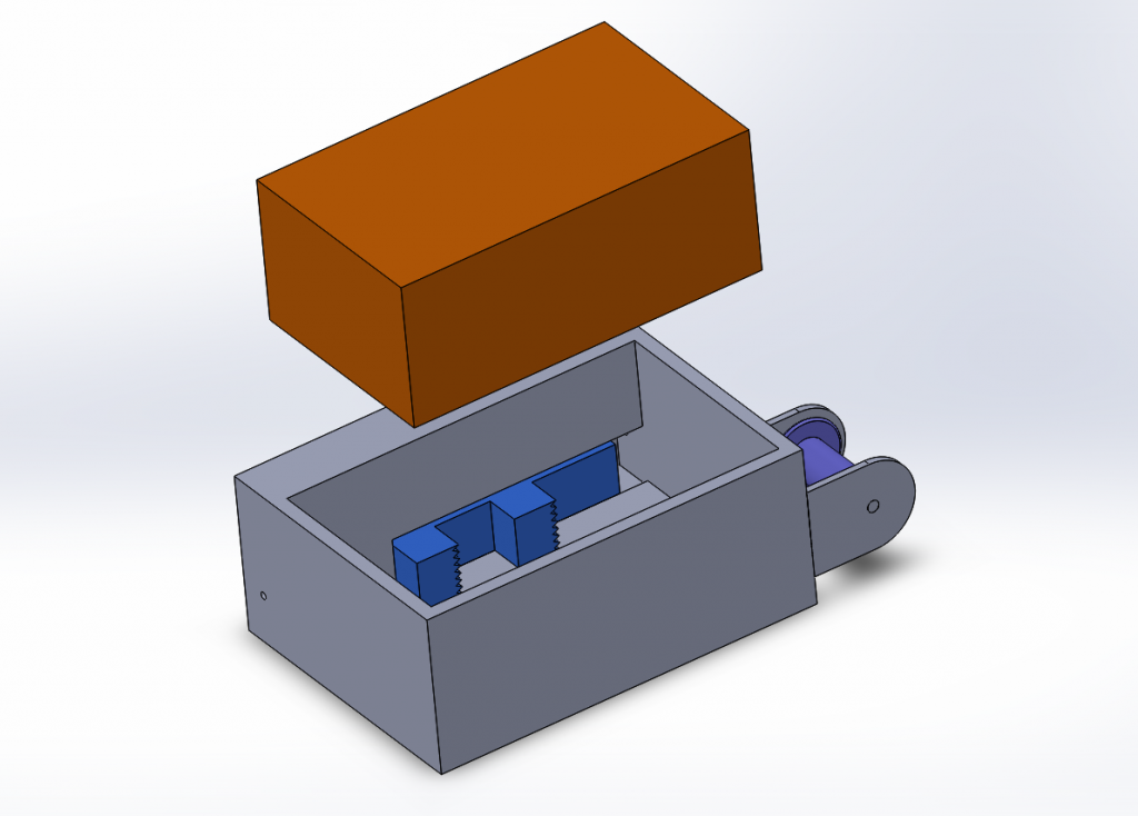
Pictured: A simplified view of the Dead-Man Buoy (DMB) system
Data Acquisition System (DAQ)
The data acquisition system aims to provide a unified platform for collecting, storing, and distributing data from instrumentation in the submarine. The data collected on Icarus is acceleration, angular velocity, orientation, depth, RPM, and battery level from an inertial measurement unit (IMU), pressure sensor, hall-effect tachometer, and the power management system respectively. All data is logged with the real time to a MicroSD card. Data collected by this system are sent to the computer aided vision system as an overlay as well as the Ballasting Assistive Device (BAD), an external LED display which displays key information involving the current orientation and direction of movement of the submarine.