Skookumchuck Mk. V
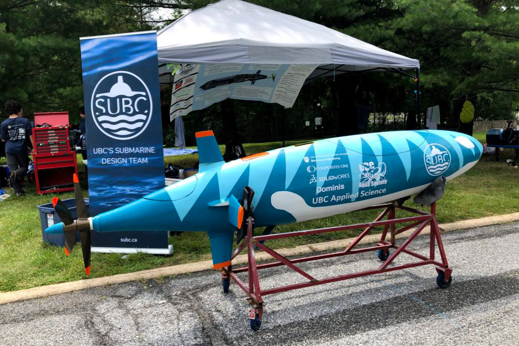
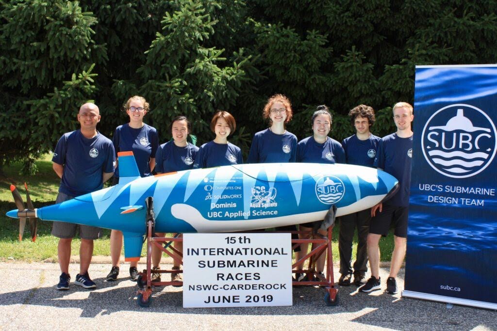
Skookumchuck Mk. V was designed and built over a 2-year period to compete in ISR 15. Our main goals this year were to improve reliability by redesigning several internal systems, and to test earlier and more often than in previous years to iterate through improvements faster.
Design Overview
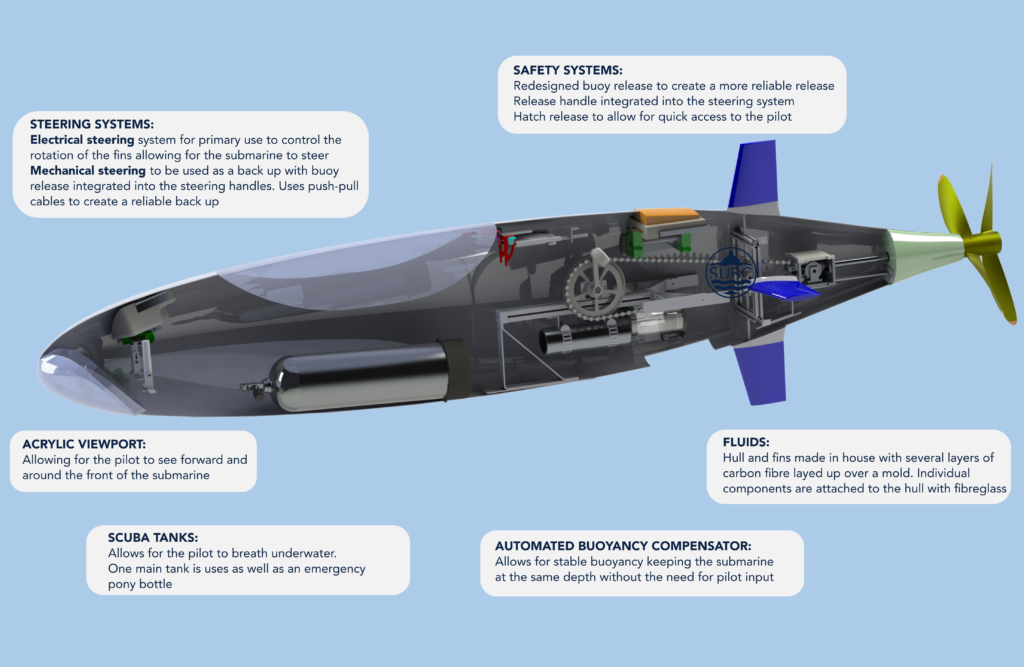
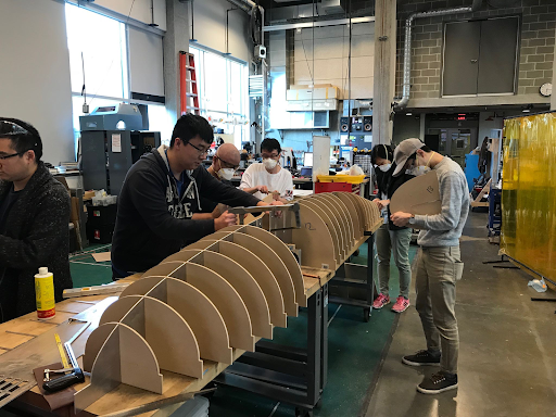
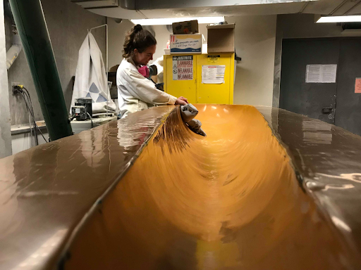
- Hull : 7-layer carbon fiber hull with a 440 litre internal capacity manufactured completely in house.
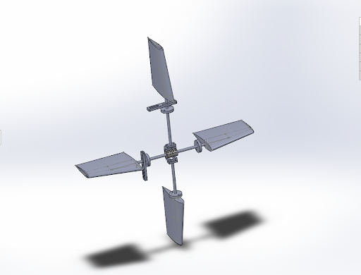
- Fins : Carbon-fiber reinforced epoxy fins set in a cruciform configuration and based on NACA 0016 airfoils.
- Drivetrain : Rotary crank driven gearbox containing spiral-bevel gears and contained in box-girder joinery-patterned aluminum housing
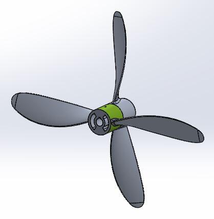
- Propulsion : Modular contra-rotating propellers that allows for multiple configurations
- Hard-anodized CNC machined aluminum 2-blade fore and 2-blade aft propellers
- 3D Printed PLA plastic 5-blade fore and 3-blade aft propellers
- Trim, Hydrostatics & Stability : Closed-cell PVC foam for coarse buoyancy adjustments and an automated buoyancy compensator for fine tuning
- Control Systems : electronic primary system and mechanical cabled secondary steering system
- Frame Structure : Aluminum frame that serves to align and integrate systems
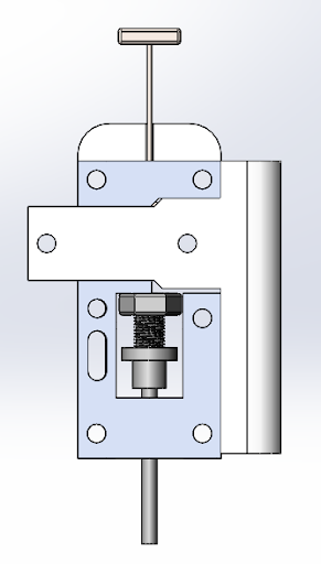
- Safety Systems : Dead-man switch activated buoy release mechanism with unique F-shaped pin design for low-profile compact size and high reliability. Buoy spool is capable of taking towing loads.
- Hatch Mechanisms : Hydraulically-actuated main hatch control and hinged systems with magnetic clasps for access hatches
Sub-Teams
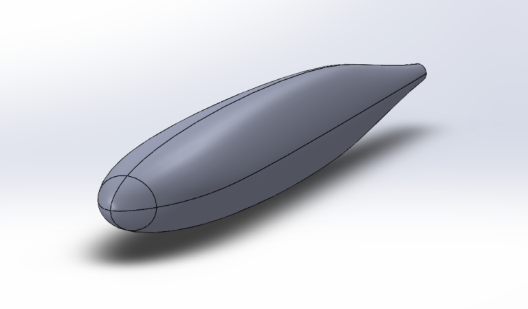
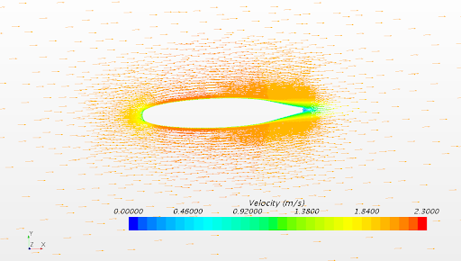
Pictured: Final CAD hull, no fins, isometric view – Sample of CFD Analysis – Manufacturing
Hull
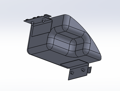
The hull is the defining component of the submarine, visually and functionally. This year’s design is a legacy system carried over from last year’s Skookumchuck IV, designed as the shape that fills two different, intersecting and perpendicular airfoils, with elliptical cross-sections of varying in size connecting the airfoils along the length axis.
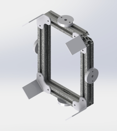
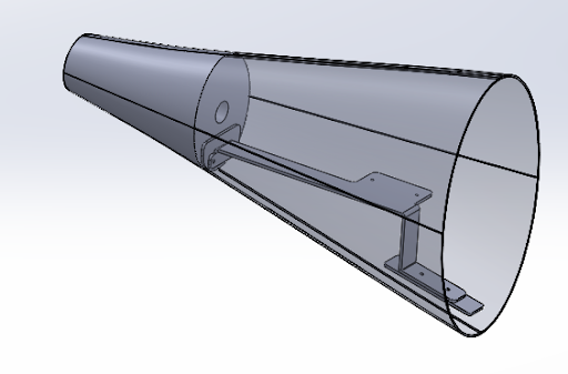
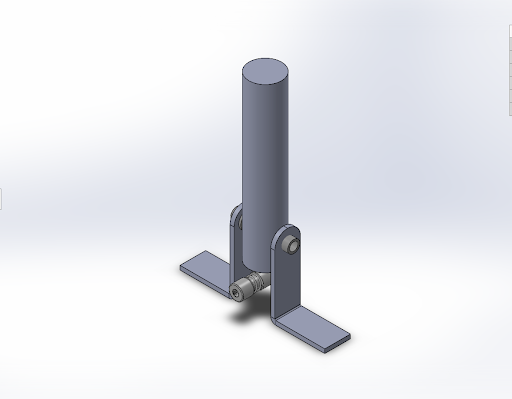
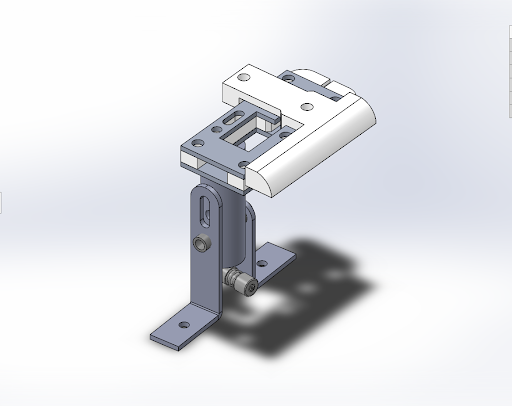
Pictured: The fin ring; corner tabs for mounting to the hull; corners of the extrusion cut to 45 degrees to conserve space – Gearbox Mount – Pedal extrusion with buoyancy compensator mount – A 3D model of the proposed shoulder pads.
Frame
The Frame was designed to support the core operating components of the submarine, and to reduce the number of mounts affixed directly to the hull. The internal frame of the submarine is comprised of four independent portions: the Fin Ring, the Gearbox Mount, the Pedal Extrusion, and the Front Mounts. Each was designed to maximize the effective space for the pilot enabling them to utilize their full range of motion when pedaling. Learning from previous iterations of the frame, care was taken to ensure its structural integrity during operation.
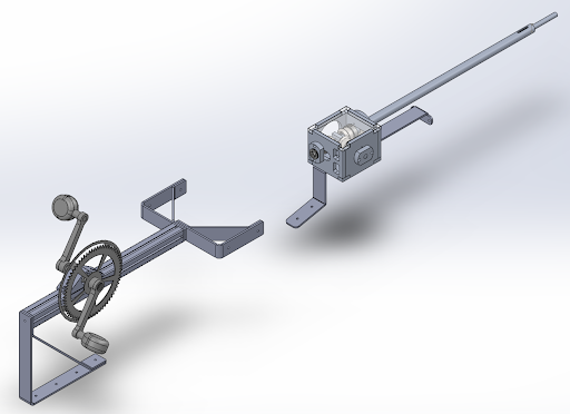
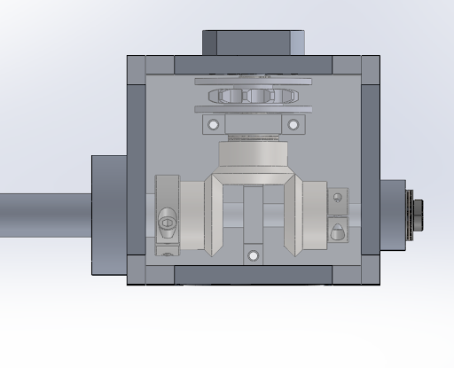
Pictured: Full drivetrain assembly – Gearbox assembly – Propeller sets in tandem
Drivetrain
Skookumchuck Mk. V employs a rotary-input drivetrain system, using a chain to connect pedals at mid-length to a gearbox at the back of the sub, and transferring the input rotation to two concentric counter-rotating shafts that power the propellers.
Pictured: Fin configuration and connection arrangement – Single-axis dual joystick design
Mechanical Steering
The mechanical steering system is a wire based steering system designed to be a reliable backup to the electronic controls. It is controlled by two joysticks and utilizes push-pull control cables with 1” transitional length to actuate two sets of fins. Each joystick independently controls the fins for pitch or yaw.
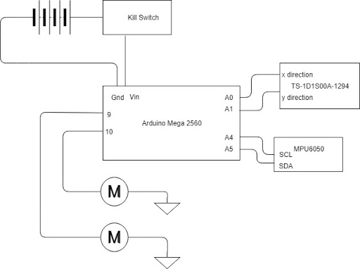
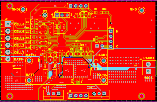
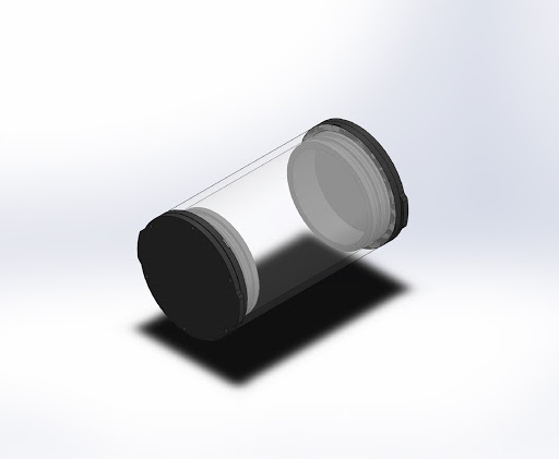
Pictured: Electrical Steering System Block Diagram – Battery Protection Module - Control Enclosure Assembly
Electrical Steering
Electrical steering provides the pilot with the capacity to maneuver the submarine left and right, while automating the diveplane control that had been left to the pilot in past years. The system uses a joystick to allow the pilot to control the submarine. Using an MPU6050 inertial measurement unit, the Arduino Mega 2560 receives the degree of pitch of the submarine, and uses feedback control to correct any unwanted changes. The system is powered by 3-series lithium-ion batteries, which can be manually disconnected by the pilot using a kill switch.
Pictured: Handle final assembly – Buoy release system – Strobe light system assembly
Safety
The safety systems are comprised of the Strobe Light System and the Buoy Release System. The strobe light system is implemented to provide the pilot with accessible light. It is comprised of a strobe light, which will be activated prior to submergence, and a strobe mount, to secure the light to the submarine. The buoy release system is implemented to alert divers on the surface to pilot distress, for instances where rescue is required. The system is comprised of a spool, a pin mechanism, a high visibility buoy and a dead man’s trigger. If the pilot has an emergency or becomes incapacitated, the dead man’s trigger will be activated, moving the pin mechanism out of constraining slots, and allowing the buoy to float to the surface. The buoy unspools high visibility rope from the spool as it ascends, providing a path to the distressed pilot.
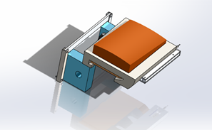
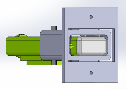
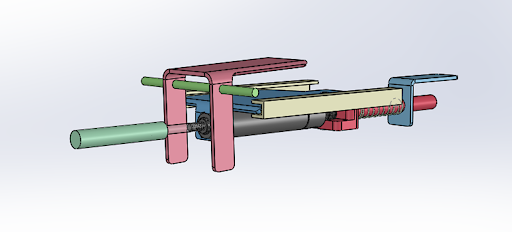
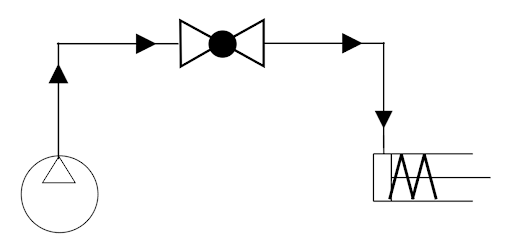
Pictured: Mechanical Components of the Hatch – Schematic Diagram of the Hydraulics Used in the Hatch
Hatch
Tubing with a ball valve and a syringe plunger are connected to the spring-loaded piston, shown in grey. The spring-loaded piston is in a retracted configuration when not actuated. This would allow for the pilot to lock or unlock the hatch by actuating or de-actuating the piston via the hydraulics that are attached. The piston itself is on a set of tracks, shown in beige, and is normally kept in place by the rod-spring configuration at its back, and the rotating fork ahead of it. However, if an external diver should want to open the hatch, the rotating plate is exposed to the exterior, and can be pulled on its end to push the piston sub-assembly backwards; this way, even if the piston is still actuated (i.e.: extended), since the piston as a whole moves, the hatch can still be unlocked.
